Convert RS-910 power supply to 12 volt
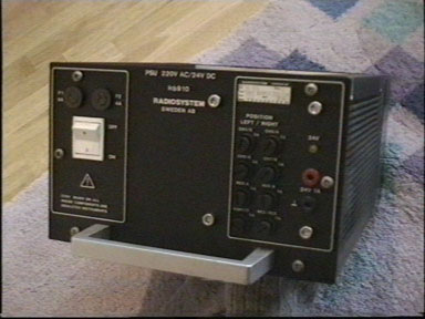
Some of the radio amateurs who have been to the Radio exhibition in Rosmalen, have past by the stand of the Museum of Cor Moerman. He sold some ex-telecom network radio's with the 24 Volt, 19 amps power supply's. These power supplies are fairly RF resistant for little money. On one evening i had the idea of converting this power supply to 12 Volt. This was easily done. With the following guide this job is no problem.
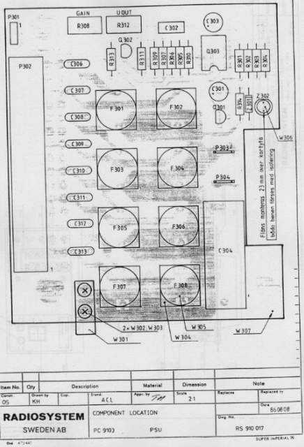
Parts layout
1. Open up the right end (three screws on front and 3 screws on back) and pull this heat sink (with a little force) from the top and bottom side. Unscrew on the circuit board the four allen screws from the front. Pull all the cables and don't forget to unscrew the clamp on the backside of the circuit board. (this is the +24 Volts transit from the main circuit board to the circuit breakers).
Modification of the regulator board in three stages:
2. Modification of the exit voltage
The exit voltage is located on the voltage divider on pin 6 of LM358. On pin 5 is a reference voltage supply by Q302. In edition this reference voltage is 12 Volts and we bring this down to 6 volts by reducing R311. Replace R311 (82 K) with 27 K.
3. Modification of the high voltage protection
The power supply has a high voltage protection on the output. As soon as the output voltage reaches a certain level, the power supply will start alternation to limit the output voltage.
A part of the output voltage goes trough a voltage regulating network (R302/R304) to pen 2 of LM358. To adjust the fold back point to 15,5 volts we just place a resistor of 18 K on the open spot from R303.
4. To illuminate the voltage led at 12 volts.
Originally the led has a 470 Ohm resister on a 15 Volt diode at the output. For the led to illuminate at 12 Volt, we remove the diode and replace it with a 220 Ohm resistor.
Now we can test our modification. Put together the circuit boards and connect the wires. The polarity of the 3 wire plug is not importent because it's wired symmetrically. Don't forget to tighten the allen screws for grounding, this is done trough this part. If the grounding is faulty the TL431 will explode and the LM358 will give smoke signals. If all goes well you can adjust the exit voltage through R312 (beside the 15 uF capacitor). Above 15,5 volts the power supply will alternate its exit voltage. The current that the power supply will sustain is minimum 19 amps. I have tested this modification for at least 1/2 an hour with 28 amps, with no problems occurring. It's a good idea to replace the original wiring from the fuses to terminals with 6 mm2 (NO 4 SWG). You can put all the fuse terminals parallel and place 3,15 to 4 amps fuses in the terminals.
I have modified a couple of these power supplies and all work well.
The performance of this power supply in combination is very good, no interference can be heard on the receiver, and no emissions are found from the power supply.
Joost Vossen, PE2JVS
pe2jvs@hotmail.com